Most problems with building-integrated photovoltaics (BIPV) roofs are not caused by incorrect structural calculations, but by getting the layout sequence wrong.
A common approach is to lay out the purlins according to the building design, choose a convenient round-number spacing—such as 1.5 m or 1.2 m—and then install the PV modules on top. Halfway through installation, the team may discover that a support point falls within 100 mm of a module edge, or that a fastener lands on a weak area of the module frame. The drawings must be revised, calculations repeated, and the project schedule may be delayed by two weeks.
The correct sequence is the reverse: determine the module dimensions first, establish the number of support lines, calculate the purlin spacing, and only then select the purlin sections.
This guide explains the entire process, provides reference ranges for purlin spacing, section sizes and steel consumption, and shows why deflection often becomes the governing design constraint before strength does.
PV Module Dimensions Determine Support Lines, Which Determine Purlin Spacing
Two Basic Support Arrangements
A PV module measuring 2,278 × 1,134 mm can be supported on purlins in two basic configurations.
| Support Arrangement | Module Orientation | Supported Edges | Purlin Spacing |
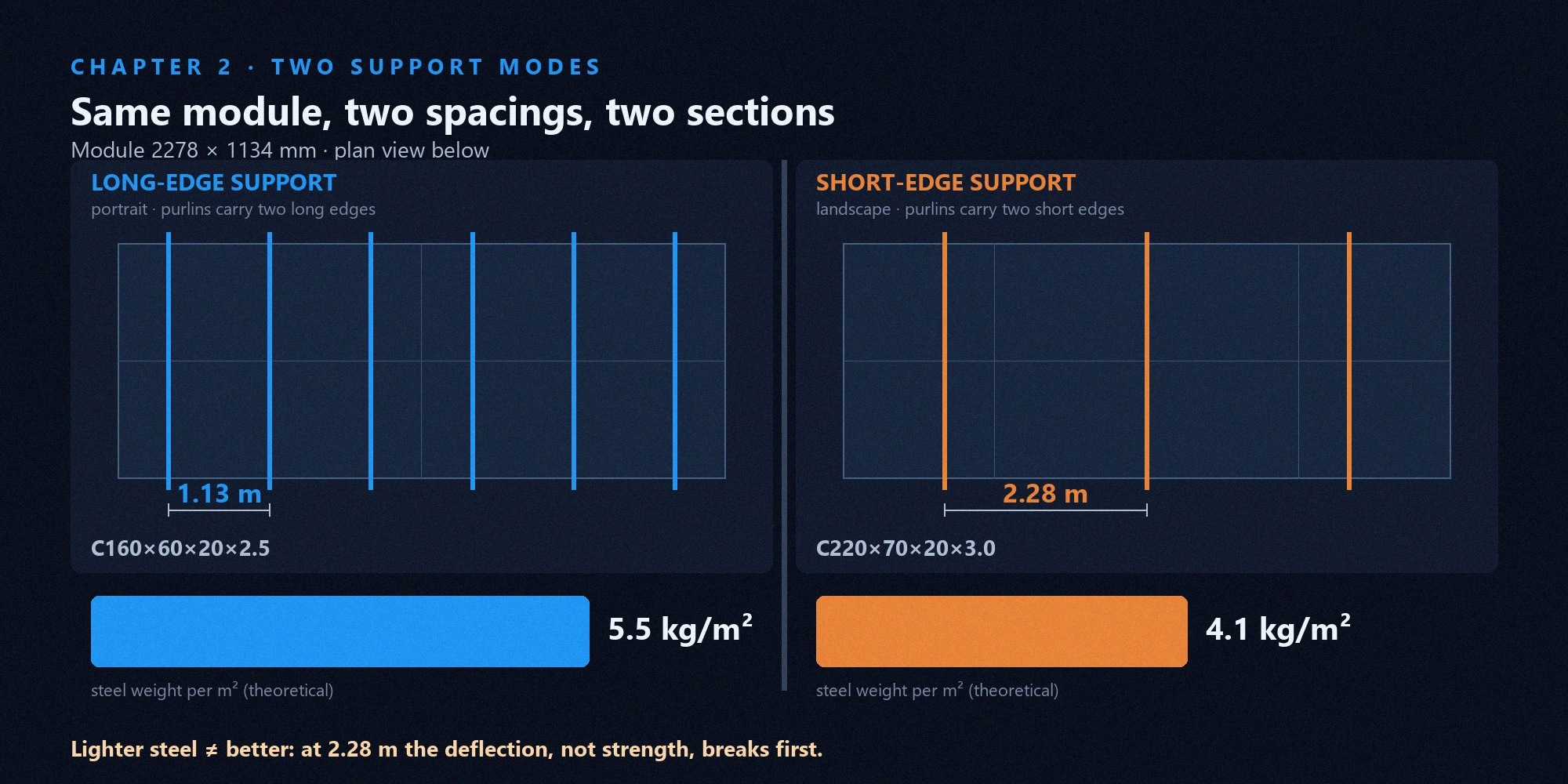
| Long-edge support | Landscape orientation | Two long edges | Equal to the module’s short side, approximately 1.13 m |
| Short-edge support | Portrait orientation | Two short edges | Equal to the module’s long side, approximately 2.28 m |
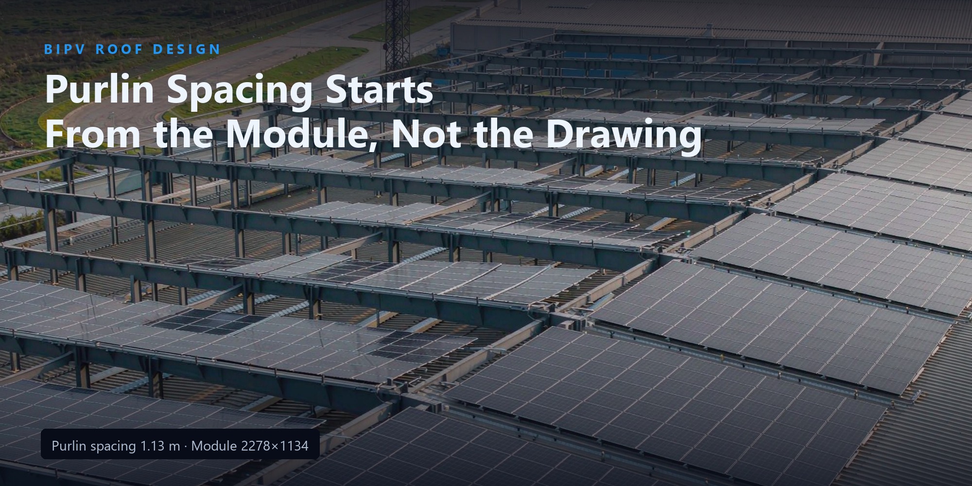
Purlin spacing is not an arbitrary design choice; it is derived from the module layout. With a module short-side dimension of 1,134 mm, the corresponding spacing is approximately 1.13 m. With a long-side dimension of 2,278 mm, it is approximately 2.28 m. There is no intermediate support line in either basic arrangement unless a third support is added.
When Are Three Support Lines Required?
For large spans, high wind loads or heavier modules, two-point support may be insufficient. One solution is to add a purlin beneath the middle of the module, dividing the original span into two spans.
With a central purlin added, the spacing between support lines becomes approximately 1.14 m or 1.13 m, producing a configuration similar to long-edge support. The trade-off is that more purlins are required, increasing the total steel consumption.
Edge-Distance Constraints
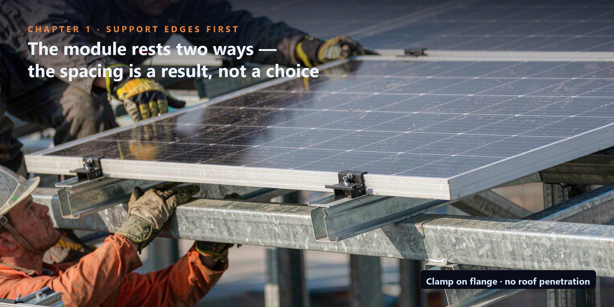
Sufficient distance must be maintained between the module edge and the purlin centerline. Typical clamps have an effective gripping width of approximately 30–40 mm. If the purlin centerline is too close to the module edge, the clamp may not grip securely. If it is too far away, the module overhang becomes excessive, increasing the risk of deformation at the corners under wind uplift.
A common industry practice is to position the purlin centerline 50–100 mm inward from the module edge while ensuring that the overhang does not exceed one-fifth of the module’s short-side dimension.
How Purlin Spacing Affects Section Selection
When purlin spacing doubles, the line load carried by each purlin also doubles, assuming the same area load. The section size must be increased accordingly.
| Purlin Spacing | Typical Section | Theoretical Weight | Steel Consumption per Unit Area | Notes |
| 1.13 m | C160 × 60 × 20 × 2.5 | Approx. 6.3 kg/m | Approx. 5.5 kg/m² | More purlins, lower load per member and easier handling during installation |
| 1.50 m | C180 × 70 × 20 × 2.5 | Approx. 7.1 kg/m | Approx. 4.7 kg/m² | A compromise solution; deflection must be checked |
| 2.28 m | C220 × 70 × 20 × 3.0 | Approx. 9.4 kg/m | Approx. 4.1 kg/m² | Fewer purlins, higher load per member; deflection may become the limiting factor |
Based on steel consumption alone, short-edge support with a 2.28 m spacing appears more economical at approximately 4.1 kg/m²—over 20% less than the 5.5 kg/m² associated with long-edge support.
However, this figure should not be considered in isolation. The reason becomes clear in the next section.
Deflection: The Limit That Can Be Reached Before Strength Becomes Critical
How Is the Deflection Limit Determined?
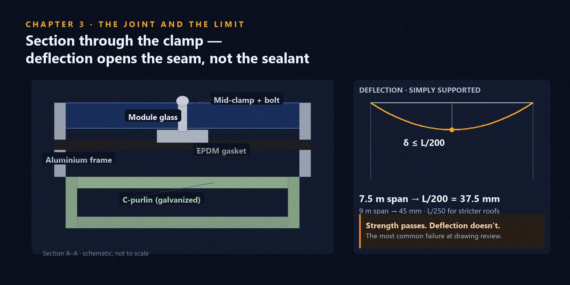
For roof purlins under normal serviceability conditions, a commonly used industry limit is L/200. Some projects with stricter wind-uplift resistance and waterproofing requirements may adopt L/250.
For a project with a 7.5 m span, L/200 permits a deflection of only 37.5 mm. For a 9 m span, the limit is 45 mm. These allowances are relatively restrictive for steel members.
Why Does Doubling Purlin Spacing Make Deflection More Difficult to Control?
Deflection is proportional to the uniformly distributed load and inversely proportional to the member’s second moment of area, assuming the same span and support conditions.
When purlin spacing increases from 1.13 m to 2.28 m, the line load on each purlin approximately doubles, as does the deflection under otherwise unchanged conditions. Increasing the section from C160 to C220 provides only a limited increase in the second moment of area, which may not fully compensate for the additional load.
As a result, the strength check may still satisfy the allowable limit while the deflection check fails. This is one of the most common roof-purlin design problems and is often discovered only during drawing reviews.
Why Are Deflection Requirements More Stringent for BIPV Roofs?
In a building-applied photovoltaics (BAPV) system, PV modules are mounted on a support structure that is then attached to the metal roof. Excessive deflection may compromise the seals between the support structure and the roof panels, creating a maintenance issue that can sometimes be addressed by resealing or replacing gaskets.
In a BIPV system, the PV modules themselves form part of the roof envelope. If a purlin deflects by 5 mm, the panel joint may open by 5 mm. Waterproofing continuity depends on structural stiffness as well as sealing details.
This is why BIPV roofs often require tighter deflection control than conventional metal roofs, and why short-edge support arrangements may be rejected on projects with large column spacing.
Three Additional Constraints That Can Change Purlin Spacing
Column Spacing
The purlin span is determined by the spacing between the main-frame columns. Column spacings of 6 m, 7.5 m and 9 m are common options for industrial buildings.
As column spacing increases, the purlin span becomes longer, generally requiring deeper sections and increasing steel consumption. Purlin spacing must therefore be selected within the framework of the established column layout rather than independently.
PV Module Joints
Purlin positions must align with the joints between PV modules. If a purlin falls directly beneath the middle of a module, fasteners may land on an unsupported area of the module backsheet, leaving the connection dependent on clamping and potentially reducing joint stiffness.
During panel layout, mark the module joint lines first and then establish the purlin centerlines. This sequence should not be reversed.
Thermal Movement
When roof temperatures reach 70°C, steel purlins and aluminum module frames expand at different rates because their coefficients of thermal expansion differ. Their longitudinal expansion is therefore not identical. A common engineering approach is to incorporate sliding details along the longitudinal direction, allowing limited relative movement between the modules and purlins.
Excessively tight purlin spacing may restrict this movement and increase restraint stresses in the module frames. Therefore, closer purlin spacing does not automatically mean a safer design.
A Complete Purlin Selection Example
Assumed conditions: a 7.5 m column spacing, an integrated BIPV roof, PV modules measuring 2,278 × 1,134 mm, and a project located in a moderate wind-pressure zone.
Step 1: Select the support arrangement. A 7.5 m column spacing is relatively large. With short-edge support and a purlin spacing of 2.28 m, deflection may be difficult to control under an L/200 limit. Long-edge support in landscape orientation is therefore selected, with a purlin spacing of 1.13 m.
Step 2: Select the purlin section. Using a dead load of 20 kg/m², a maintenance live load of 0.5 kN/m² and the applicable local wind-load combinations, calculate the line load and select a C160 × 60 × 20 × 2.5 section. If wind pressure is higher, upgrade to C180 × 70 × 20 × 2.5.
Step 3: Verify deflection. For a 7.5 m span, the L/200 limit is 37.5 mm. Check the deflection under the applicable load combinations and confirm that it remains within the permitted limit.
Step 4: Align the module joints. Arrange the modules using a 1,134 mm layout module. Align the purlin centerlines with the module joint lines, with a target positioning tolerance of ±5 mm.
Step 5: Complete the layout drawings. Clearly indicate purlin spacing, section specifications, fastener positions, sliding ends and fixed ends.
Following this sequence helps reduce the likelihood of layout revisions during drawing reviews.
Frequently Asked Questions
Q1: What is the typical spacing between roof purlins?
A common industry range is 1.0–1.5 m. The actual spacing depends on module dimensions, support arrangements and load combinations. For a module with a short-side dimension of 1,134 mm, long-edge support corresponds to approximately 1.13 m spacing. Short-edge support based on a long-side dimension of 2,278 mm corresponds to approximately 2.28 m, which exceeds the usual range and requires a separate deflection check.
Q2: Does smaller purlin spacing always make the roof safer?
No. Smaller spacing means more purlins and higher steel consumption. It may also restrict the sliding movement required to accommodate thermal expansion, increasing restraint stresses in the module frames. The correct approach is to satisfy deflection, strength and thermal-movement requirements simultaneously.
Q3: Can a BIPV roof use the same purlin layout as a conventional metal roof?
This is not recommended without a specific design review. Deflection limits for conventional metal roofs primarily address drainage and appearance, whereas BIPV roofs must also maintain continuity between the PV modules and the waterproofing system. The same purlin arrangement may be adequate for BAPV but may cause panel joints to open excessively in a BIPV application.
Q4: Should purlins be added or spaced more closely when retrofitting BIPV onto an existing factory roof?
The existing structure must be reassessed based on the original design loads and its current corrosion condition. Industry experience suggests that fewer than half of existing metal roofs pass the structural capacity checks required for PV retrofits. Where a structure fails, reinforcement may be necessary, including increasing member capacity, adding supports or replacing purlins. These measures can account for 15%–25% of the retrofit budget.
Integrating PV dead loads and maintenance live loads at the structural design stage can reduce total steel consumption by approximately 8%–12% compared with a design that requires subsequent reinforcement. This estimated saving results from the combined effects of shared connection details, section optimization and integrated roof design. It excludes differences in the cost of the PV modules themselves.
Contact: info@xzbesta.com