For off-grid projects, the first question is almost always the same: How much power does my mobile solar power station need?
There is no one-size-fits-all answer. The required power rating must be calculated, not simply selected. One incorrect assumption can lead to costly rework: an undersized system may fail to support the load, while an oversized system ties up capital in capacity that may never be used.
This guide breaks down the sizing method, provides a quick-reference table for common operating scenarios, and explains why PV modules, inverters and energy storage must be calculated separately.
Start by Calculating Three Key Values
Daily Energy Consumption (kWh/day)
This is the starting point for all sizing calculations. What matters is the actual electricity consumed over 24 hours—not the sum of equipment nameplate ratings or the number of devices multiplied by their rated power.
There are three ways to estimate consumption on site:
- Check historical meter readings.This is generally the most accurate method for projects with an existing grid connection or diesel generator.
- Calculate from an equipment list.Estimate each device’s energy consumption by multiplying its rated power by its daily operating hours.
- Use comparable projects as a reference.
The third method is commonly used for newly established construction camps or mining sites. Typical industry estimates are: 30-person construction camp: 60–120 kWh/day; 100-person construction camp: 250–400 kWh/day.
Peak Power and Demand Factor
Peak power determines the required inverter capacity, while daily energy consumption determines the required PV capacity. These are two different parameters.
On-site equipment does not normally operate at full load simultaneously. A demand factor of 0.6–0.8 is commonly used in engineering estimates. Assuming a demand factor of 1.0 may result in an oversized inverter, leaving excess capacity unused throughout the project lifecycle.
One important consideration is equipment with high-power motors, such as water pumps, crushers and lifting equipment. Their starting current must be calculated separately. The instantaneous starting current of an induction motor using direct-on-line starting can reach 5–7 times its rated current. If this issue is not addressed, even an otherwise adequately sized inverter may trip its protection.
Nighttime Energy Consumption as a Percentage of Daily Use
This figure determines the energy storage configuration. For camps that are largely unoccupied during the day but consume significant electricity at night, nighttime consumption can often exceed 50% of daily use. For pumping stations that operate mainly during daylight hours, the nighttime share may be below 20%.
The lower the nighttime share, the more storage serves as a supplementary function. The higher the share, the more critical energy storage becomes to the overall system.
Quick Power Reference for Common Operating Scenarios
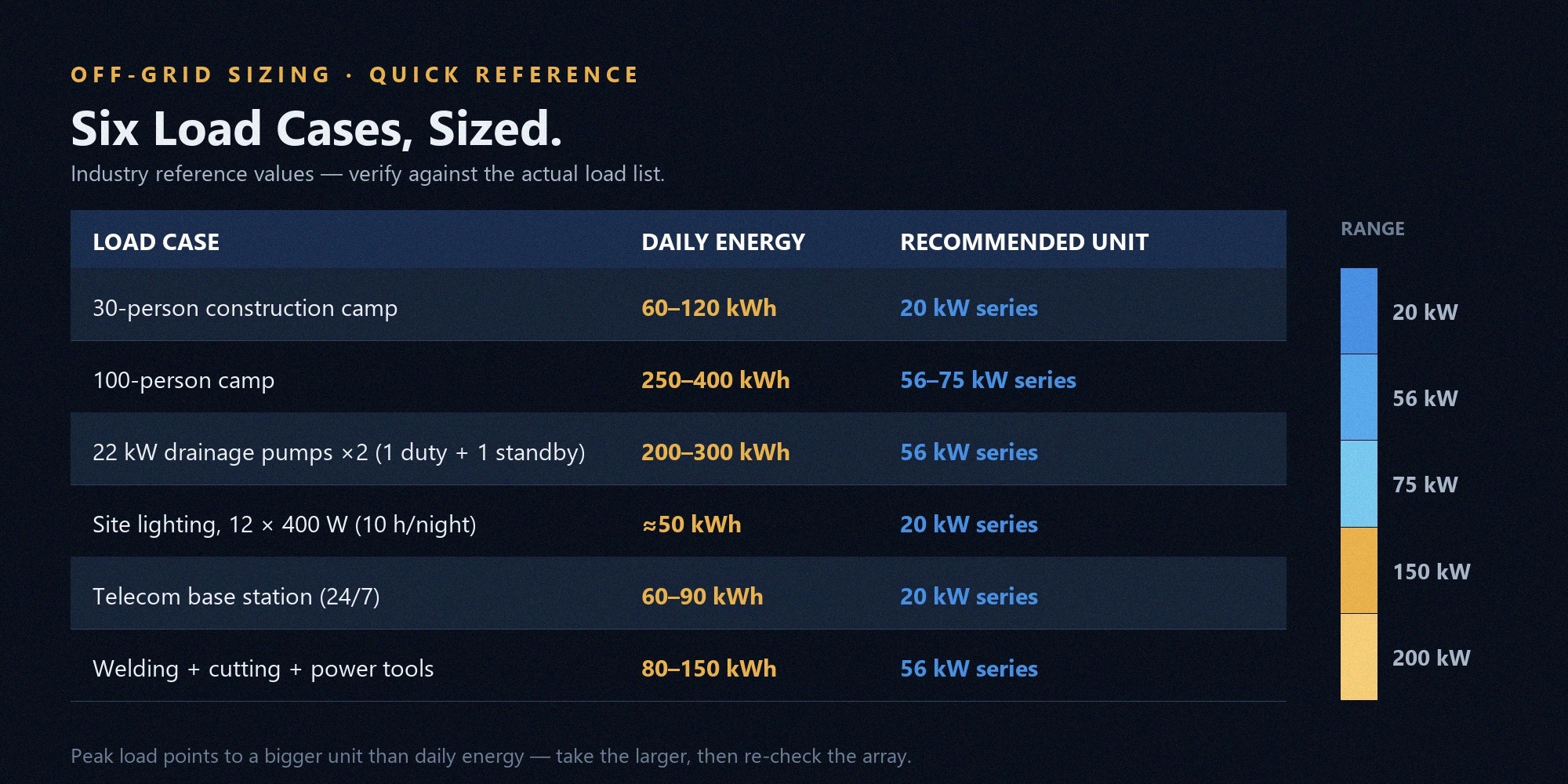
The following table summarizes typical ranges for six common operating scenarios. These figures are based on industry experience; actual project requirements must be verified against the load list.
| Operating Scenario | Daily Energy Consumption (kWh) | Peak Power (kW) | Nighttime Consumption | Recommended PV Capacity | Recommended Energy Storage |
| 30-person construction camp | 60–120 | 15–25 | 50%–60% | 20 kW series | 40 kWh |
| 100-person construction camp | 250–400 | 50–70 | 50%–60% | 56–75 kW series | 121 kWh |
| Two 22 kW drainage pumps (one operating, one standby) | 200–300 | 40–50 | Below 20% | 56 kW series | Optional, as required |
| 12 × 400 W site lights (10 hours at night) | 50 | 5 | 100% | 20 kW series | 40 kWh |
| Telecommunications base station (24/7 operation) | 60–90 | 3–5 | 100% | 20 kW series | 40 kWh |
| Welding machines, cutting equipment and small power tools | 80–150 | 20–40 | Around 30% | 56 kW series | Optional, as required |
To use this table, first identify the operating scenario and check which range matches the daily energy consumption. If peak power and daily energy consumption point to different system sizes, use the higher power rating as the starting point, then verify whether the PV capacity is sufficient.
Why PV Modules, Inverters and Energy Storage Must Be Sized Separately
DC/AC Ratio: PV Capacity Is Typically Higher Than Inverter Rated Output
PV module output is rated under standard test conditions: a module temperature of 25°C, irradiance of 1,000 W/m² and an air mass coefficient of AM1.5. When the module backsheet temperature reaches 65°C on site, crystalline silicon modules with a temperature coefficient of -0.3%/°C may experience an output reduction of approximately 12%–14%.
If PV capacity and inverter rated output are matched at a 1:1 ratio, the system may not reach the inverter’s rated output during the hottest part of the day, leaving some inverter capacity underutilized.
A common industry practice is to size the installed PV capacity at 1.1–1.3 times the inverter’s rated output. This ratio is known as the DC/AC ratio. It is not an inflated rating; it helps make better use of available solar irradiance.
How to Calculate Energy Storage Capacity
Energy storage capacity depends on nighttime electricity consumption and the permitted depth of discharge (DoD).
| Nighttime Consumption as a Share of Daily Use | Required Storage for 100 kWh/day of Consumption | Description |
| 20% | Approx. 22–25 kWh | Covers evening lighting and communications only, assuming a 90% depth of discharge |
| 40% | Approx. 45–50 kWh | Covers auxiliary production loads during the evening |
| 60% | Approx. 67–75 kWh | For around-the-clock operating scenarios, with additional capacity reserved for cloudy or rainy days |
| 100% (telecommunications base station) | Approx. 110–120 kWh | Requires design consideration for 2–3 consecutive cloudy or rainy days |
The calculation can be expressed as:
Energy storage capacity = Daily energy consumption × Nighttime consumption share ÷ Depth of discharge × Cloudy-weather reserve factor (1.0–1.3)
The redundancy factor can be verified against local meteorological data using the JRC PVGIS off-grid system module.
For lithium iron phosphate (LFP) batteries, a typical depth-of-discharge design value is 90%. Do not calculate on the assumption of 100% DoD, as this can compromise cycle life.
Cycle Life and Replacement Schedule
Lithium iron phosphate batteries can achieve 5,000–8,000 cycles at an 80% depth of discharge. Assuming one charge-discharge cycle per day, this corresponds to approximately 13–21 years. This is shorter than the nominal 25-year service life commonly specified for PV modules. Energy storage may therefore require replacement during the system’s lifecycle and should not be overlooked in investment calculations.
Matching Your Project to One of the Six Product Series
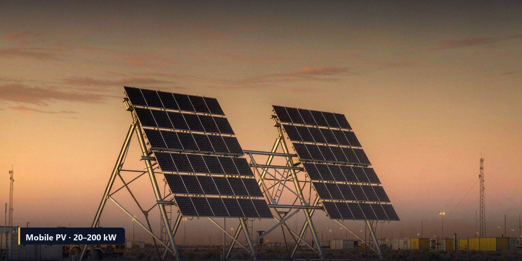
ZM-Besta’s mobile solar power stations are available in six power series, covering 20 kW to 200 kW, with 24 models in total. Key specifications are listed below.
| Series | Installed PV Capacity | PV Module Type | Power per Module | Deployed Footprint | Product Weight (Excluding Energy Storage) | Standard Energy Storage |
| 20 kW | 15–20 kW | N-type TOPCon | 690–720 W | 33–39 m × 4 m | 3.8–4.3 t | 40 kWh |
| 56 kW | 40–56 kW | N-type TOPCon | 440–460 W | 63–85 m × 6 m | 12.5–15 t | 121 kWh |
| 75 kW | 56–77 kW | N-type TOPCon | 440–460 W | 63–85 m × 6 m | 12–15 t | Optional, as required |
| 150 kW | 109–152 kW | N-type TOPCon | 510–530 W | 70–96 m × 12 m | 33–36 t | 261 kWh |
| 175 kW | 133–175 kW | N-type TOPCon | 510–530 W | 70–96 m × 12 m | 31–34.5 t | Optional, as required |
| 200 kW | 148–204 kW | N-type TOPCon | 580–600 W | 85–110 m × 12 m | 31–34 t | Optional, as required |
Common specifications across the product range:
- Installation angle: 25°
- Frame included angle: 130°
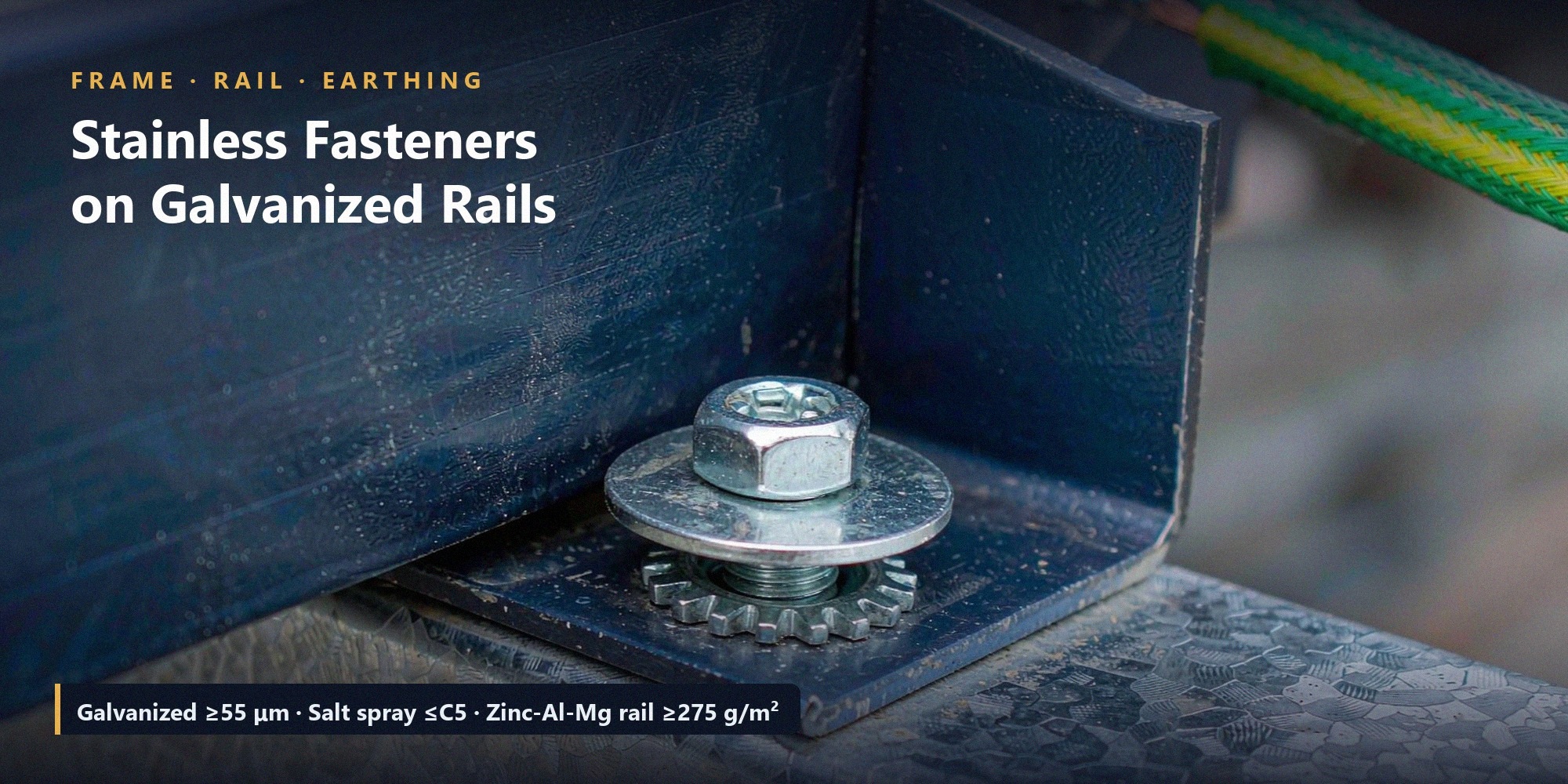
- Hot-dip galvanized coating on the frame: ≥55 μm
- Zinc-aluminum-magnesium coating on guide rails: ≥275 g/m²
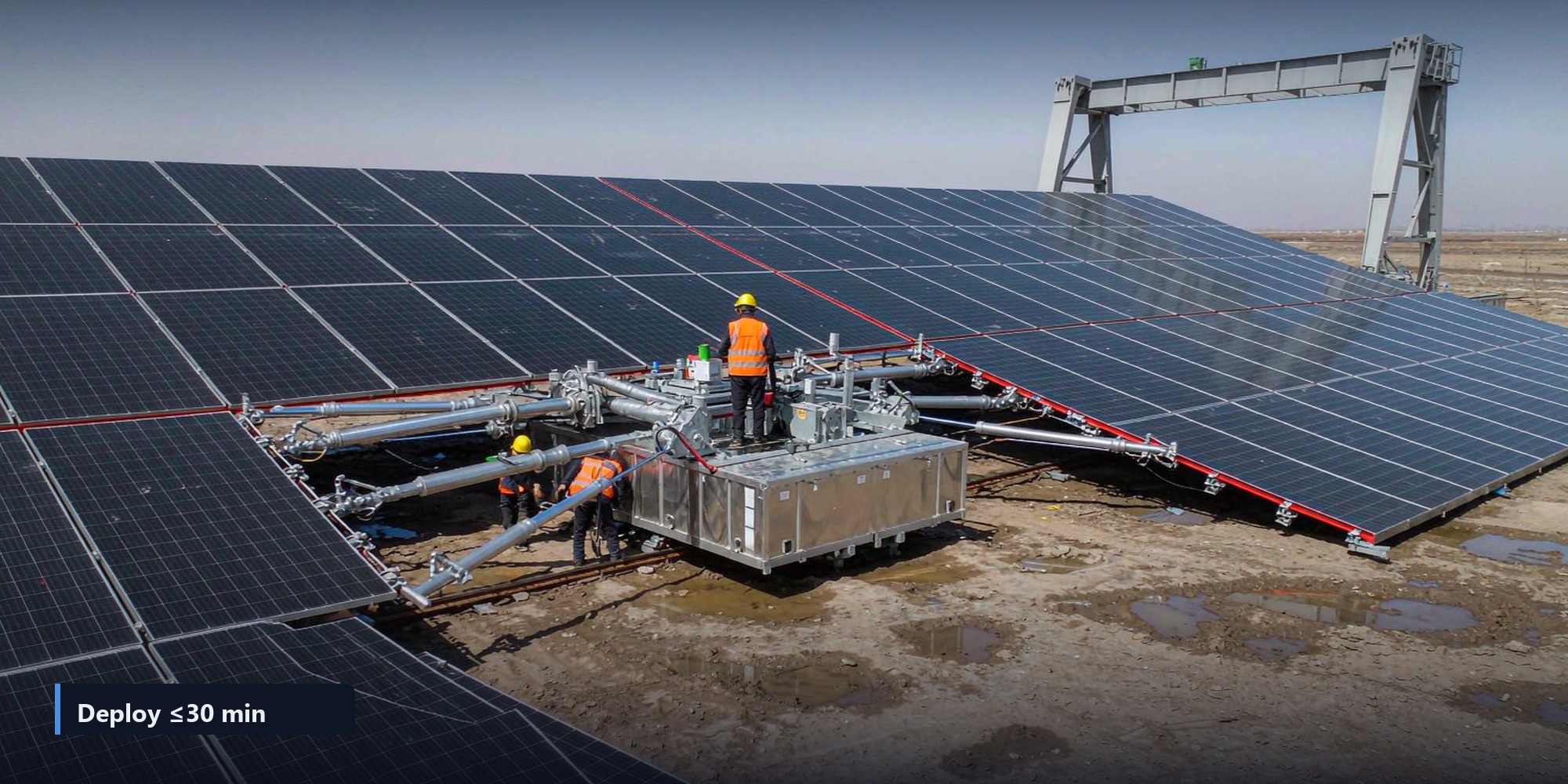
- Deployment time: ≤30 minutes
- Wind resistance after deployment: Grade 9
- Salt-spray resistance: ≤C5
- Operating temperature: -20°C to +50°C
- Protection rating in the stowed configuration: IP55
- Hybrid inverter output: 380 V/400 V, three-phase, four-wire
- Frequency: 50/60 Hz
Four Common Sizing Mistakes to Avoid
Simply Adding Up Equipment Nameplate Ratings
Adding the rated power of every item on the equipment list typically produces an estimate that is 30%–50% too high. Equipment does not all operate simultaneously, and the difference can translate directly into unnecessary system costs.
Ignoring Temperature-Related Output Losses
In desert mining areas with ambient temperatures of 45°C, PV module backsheet temperatures can exceed 70°C, reducing output by nearly 15%. Sizing a system based on the standard rating at 25°C can result in a lower-than-expected actual output.
Sizing Energy Storage for Peak Load
Energy storage accounts for a substantial proportion of the total system cost. Sizing storage according to peak power means paying for an entire day’s storage capacity to cover a peak that may occur for only two hours. The correct approach is to size storage based on nighttime energy consumption.
Overlooking Transportation and Lifting Requirements
Equipment with a deployed footprint of 110 m × 12 m and a weight of 34 t requires advance checks of site access roads, turning radius and crane lifting capacity. Temporary roads at mining sites are often designed for light vehicles. If heavy-vehicle access and unloading requirements are overlooked, the equipment may arrive on site but be impossible to unload.
Frequently Asked Questions
Q1: How much electricity can a 20 kW mobile solar power station generate per day?
Generation depends on local solar conditions. Assuming 4.5 peak sun hours and a system efficiency of 0.75–0.8, each 1 kW of installed PV capacity generates approximately 3.4–3.6 kWh per day. A 20 kW system would therefore generate approximately 68–72 kWh/day. In areas with 5.5 peak sun hours, daily generation may reach around 85 kWh.Actual local PVOUT can be queried by coordinate in the Global Solar Atlas.
Q2: Can the system directly power motor-driven loads?
Yes, but starting current must be calculated. A 22 kW induction motor using direct-on-line starting may draw an instantaneous current of 110–150 A. The inverter must have sufficient overload capability to handle this demand. For high-power motors, a soft starter or variable frequency drive (VFD) is recommended to reduce starting current and the associated electrical surge.
Q3: Can the system operate without energy storage?
Yes. For applications that mainly consume electricity during the day, such as pumping stations and crushing operations, the system may operate without energy storage, with the inverter supplying power in response to the load. However, applications that require backup power at night or during cloudy weather need energy storage.
Q4: Can the system be expanded?
The modular design supports capacity expansion by adding and connecting additional units in parallel. Before expansion, check the inverter’s maximum permitted number of parallel units and the capacity of the connection point. Adding PV capacity alone without upgrading the electrical distribution system may not be sufficient.
Q5: How long can the equipment operate in a salt-laden environment?
The product range is specified with a salt-spray resistance rating of ≤C5 and a hot-dip galvanized frame coating of ≥55 μm. Under ISO 12944 corrosion classifications, C5-M refers to highly corrosive marine environments, including certain coastal locations within 500 m of the sea. With this protection level and regular inspections, the system may support a service period of more than 15 years. The actual service life still depends on site-specific corrosion conditions and maintenance frequency.
Contact: info@xzbesta.com